| Active Vibration Damping Experimental Setup - as of 07.09.2007 |
|
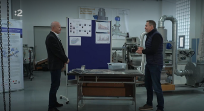
Active vibration control / damping experimental setup at the Department of Automation, Informatics and Instrumentation of the Faculty of Mechanical Engineering, at the Slovak Technical university. Please note that the lab setup is currently under construction and development. Check out the video and the pictures, for more info contact Gergely Takacs: gergely.takacs@stuba.sk |
 |
|
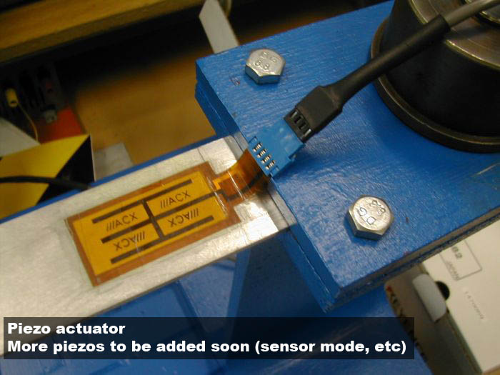
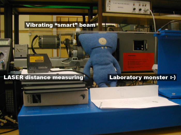
The picture shows the lab setup as a whole in its current state. (07.09.2007) Currently the rest of the PZT actuators / sensors are already in place, the picture shows only one piezo bonded to the beam.
|
 |
|
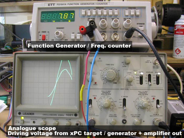
A function generator (ETT FG1641A) is used during the initial tests of the piezo and its response to different frequencies. Naturally the control will be implemented on a PC utilizing a DAQ card. The generator will be used also at when preparing the system model.
|
 |
|
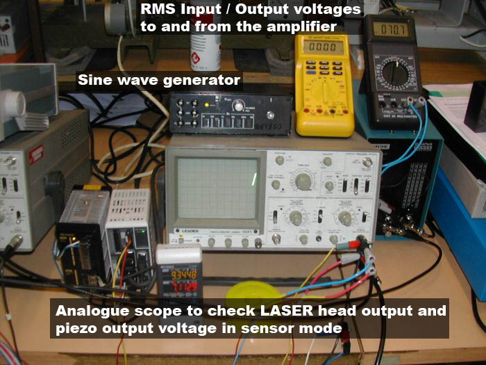
A second two channel analogue scope (Leader 1021) is used to monitor the analogue output from the LASER distance measuring head. The second channel of the scope will be utilized to monitor the voltage output from another PZT patch, used as a sensor. Note that the control moves will be calculated according to the signal from the piezo patch and not from the LASER vibrometer. This is only used for modelling and validation purposes.
|
 |
|
The image shows a Mide QP16n piezo actuator bonded to the aluminium beam's surface. The wire connections have to be revised in the future, to minimize interaction with the beam dynamics.
|
 |
|
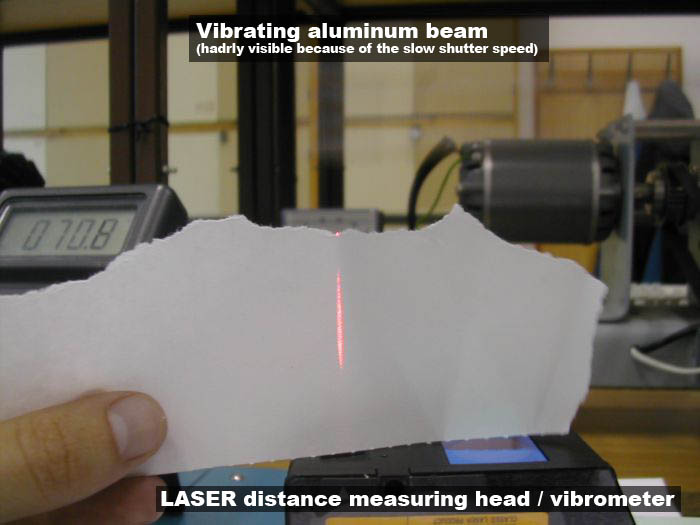
You may see the LASER beam from the measuring head. (there are actually two heads to our disposition) The vibrating aluminium beam is hardly visible because of the slow shutter speed of the camera. At the first resonance mode, the tip of the beam moves +-12 mm from the reference position. This displacement seems enermous, compared to the static displacements, which may be produced with the piezo in normal conditions.
|
 |
|
Note that the variable position LASER head fixture is currently beeing manufactured in the university workshop. The massive base ensures that the vibrations from the Al beam don't interact with the surroundings and vice-versa.
|
 |
|
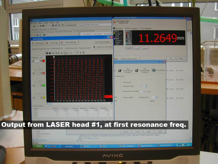
The screenshot shows the output from the LASER distance measuring system.
|
 |
|
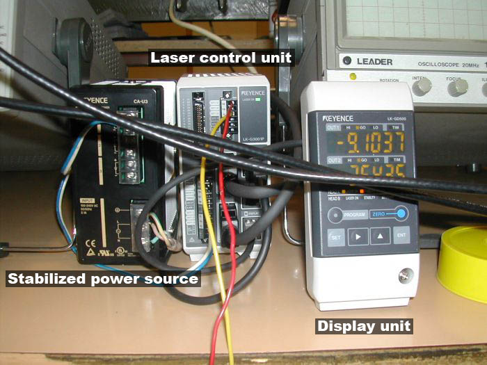
This image shows the stabilized power source which drives the LASER system (Keyence LK series), the controller unit which can control up to two heads and the display/setup unit. Currently we have two heads to our disposition: one can measure +-15 mm from the reference position with a 0.0005 mm repeatability, the other one +-5 mm with 0.0002mm repeatability... As our initial test show, measuring beyond the hundredth millimeter range is unneccesary, since the beam vibrates from the effects of the sorrounding. (People in the room, airflow, cars and street noise)
|
 |
|
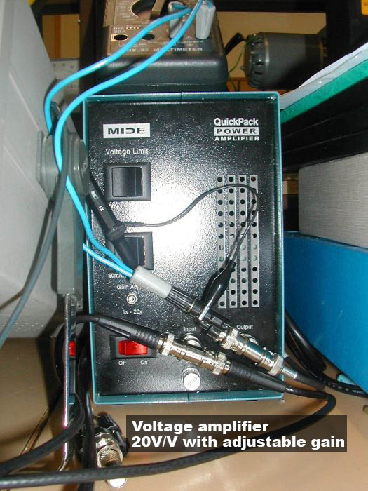
Adjustable gain power amplifier (Mide) drives the piezo. The amplifier takes an input voltage of +-10V amplitude and amplifies it from 1V/V up to 20V/V... Unfortunately the unit produces much electrical noise - this issue needs to be addressed in the future.
|
 |
|
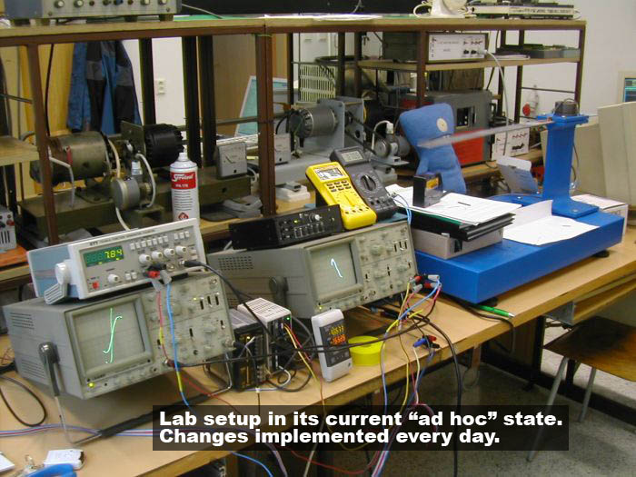
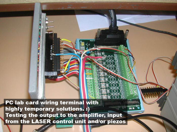
Wiring terminal from the DAQ card. Note that the setup is changed frequently, that's why the board wiring seems a "little" confusing. Soon, we will acquire a "high end" data aquisition card from NI solely for the vibration control experimental setup. Thank you for your attention. |
Gergely Takacs, 2007